RAV4 HF VHF Ham Radio Installation

Return to N5BIA Info Site

Introduction
Antenna mounting bracket
Wiring
Tuner mounting
Radio installation
Conclusion
Appendix-HP Filter
Parts list

Introduction

Our recent purchase of a new vehicle meant a new project for me - move the radio from the old car to the new RAV4. I started with Internet research to see what other RAV4 owners had done, continued with trips to the dealerships while we picked out the car, and spent several evenings planning the installation. I tend to keep cars longer than most, and I wanted a solid, reliable installation that worked well.  
I planned an installation that required  as few  permanent modifications to the vehicle as possible, with no holes to drill in the vehicle body. Good grounds, adequate wire size with adequate fuses for protection of the wiring, vehicle, and radio are a necessity for a safe mobile installation.
 I planned and executed the installation in steps so as to be able to use the vehicle while I was fabricating or gathering the parts. This worked out well – in just under three weeks in my spare time, I had the job completed. Because many of the recent SUVs have an externally mounted spare tire, my approach could easily be adapted to those vehicles also.
TOP

Antenna mounting bracket

The first order of business was to decide on how to attach the antenna to the vehicle. Permanent installation was a requirement. Mag mounts were not considered,  not even as a temporary installation.
The 'skin' on most new vehicles is much thinner than cars from the 1970s and 1980s, so ball mounts or similar mounting fixtures were out. The constant flexing would eventually take its toll unless I could figure out how to reinforce the skin from the inside.  I quickly eliminated this option.
I wasn't planning to use the vehicle for towing, so a trailer hitch just to mount an antenna seemed a bit excessive. Roof rack mounts, while marginally acceptable for VHF-UHF, can be problematic for HF. This is especially true with non-conductive roof racks or when the roof rack is attached to the body with insulating fasteners. The search continued.
The RAV4 has a spare tire mounted on the rear door, so that seemed to be worth considering. Pre-purchase inspections in the dealership confirmed the practicality of building a mounting bracket that would also enable me to keep the spare tire cover in place. This was the option I chose.
At first, I considered fabricating a mount that would fit between the spare tire mount and the vehicle. I even designed one using e-machine shop (www.emachineshop.com) software, but when I saw the price for one or two of the mounts, I continued to search for alternate methods because of the cost. That was when I came across some very heavy hurricane straps in Lowes (www.lowes.com), a local building supply store. Using four of these straps, I designed a mount that was the functional equivalent of my original design at a fraction of the cost.
TOP

Fabrication

A bit of work in the Armstrong machine shop with a hacksaw and a hand drill produced a workable antenna mount that didn't damage the budget too badly. If you have access to a band saw and a drill press, even better.
None of the local building supply stores had the 3/16 steel rivets, but a trip to a nearby Ace (www.ace.com) hardware store yielded the rivets, the stainless steel hardware, and a can of water-based latex spray paint to paint the finished product. Don't be tempted to substitute aluminum rivets - corrosion from the dissimilar metals would weaken the joints over time. I don't recommend substituting threaded fasteners to assemble the antenna mount, either.
Cut the HS-12 straps to a length of 9 13/16”. Align one of the straps  with the left edge of the A-311 strap as shown in the Figure 1. Clamp the strap in position on the A-311 and make sure the two intersect at right angles.
antenna mount front view
Figure 1 – Antenna mount front view

Using the existing nail holes in the straps as guides, drill the 3/16” holes for the pop rivets. Place the rivets, and then remove the clamps. Repeat for the upper strap as shown in Figure 2.
Align the right HS12 strap to the A-311 L-strap, and then clamp the lower strap in position and drill the 3/16” rivet holes. Place the rivets and then remove the clamp. Repeat for the upper strap.
Antenna mount top view
Figure 2 – Antenna mount top view

Test fit the antenna mounting hardware. Depending on the antenna base you choose, you may have to enlarge the two holes in the top of the antenna mount. If this is necessary, I suggest using a step drill bit. These are available in several sizes at very reasonable cost from Harbor Freight (www.harborfreight.com).
Using Figure 1 as a guide, drill a 5/16” hole in the lower cross piece HS-12. Break the sharp edges with a file or countersink.
The next step is optional because the straps are galvanized and won't start to rust immediately. Painting the finished mount will result in a better looking installation, however. This step will also prevent rust and weathering of the antenna mount.
Petroleum-based paints such as color-matched automotive touch-up paint are a poor choice for this task because petroleum-based paints do not adhere well to galvanized surfaces unless special preparation and primers are used. Ace Hardware has a good selection of colors in spray can latex paint.
Clean the finished assembly with soap and water, rinse it thoroughly with plain water, and then leave it in the sun to dry for a couple of hours. Overnight is even better. When the assembly is dry and cool enough to paint, apply two or more even coats of paint. For best results, be sure to follow the directions on the can for drying times between applications and final drying time.

Installation

Antenna bracket installation takes a couple of hours. To avoid extra removal of the spare tire,  plan on about three hours to complete the following steps in one session:
Remove the spare tire cover. To avoid damage to the finish, place it in a safe place.
Remove the spare tire.
Remove the two top spare tire mount bolts.
Remove the body panel bolt
Loosen the two bottom spare tire mount bolts. You do not need to remove the lower bolts or the spare tire mount.
Slide the antenna mount into position between the body and the spare tire mount.
Align two large holes in the antenna mount with the holes in the spare tire mount and body.
Install the new spare tire mount bolts. Hand tighten only.
Install the spacer between the lower cross brace and the body, and then install the new body panel bolt.
Installed antenna mount
Figure 3 – Installed antenna mount

Attach the grounding straps to each of the antenna mount locations.
Upper grounding lug
Figure 4 – Upper grounding lug

One at a time, remove the upper spare tire mount bolts, pass the bolt through one of the lugs on the ground strap, and then re-install the spare tire mount bolts.
Assemble the UHF/VHF and HF/6M antenna base fixtures.
Install the UHF/VHF antenna base fixture in one of the mount locations, and then install the HF/6M antenna base fixture in the remaining location.
Wind 4 to 6 turns of each antenna cable in a 8-inch loop and secure with nylon cable ties. These serve a dual purpose - a choke on each antenna cable near the antenna and as a service loop if needed. Note that coax cables are not fitted with connectors during installation. These connectors will be installed later.
Remove the nylon fitting from the door, and then enlarge the opening so that both coax cables can pass to the inside of the door. Be sure to fit a grommet to protect the antenna cables. Dress the cables so that they lay flat against the vehicle body, and then cover the opening with a small piece of duct tape to keep water out.
Coax cable feed-through
Figure 5 – Coax cable feed-through

Secure the antenna cables to the antenna mount assembly vertical members. Some split tubing and nylon cable ties make for a neat installation.
Coax cable routed through cable guide
Figure 6 – Coax cable routed through cable guide

Route the antenna cables through the existing rubber cable flexible guide near the door hinge. The flexible guide pulls out easily on both ends to make installing the cable easier. Work the ends of the guide back into the holes when you are finished.
Coax cable routing
Figure 7 – Coax cable routing

Drill a 1-inch hole in the side of the plastic cargo pan for the cabling. Route the antenna coax cables toward the bottom of the jack compartment, and then fish the coaxial cables through the hole and into the plastic cargo pan.
Make sure the plane of the antenna mounting surfaces are level, and then tighten all four spare tire mount bolts.
Place three spacer washers on each of the top two spare tire lugs. These spacers will tilt the spare out just enough so that the spare tire cover is not pinched between the tire and the antenna mount.
Reinstall the spare tire on the rear door of the vehicle. Install and securely tighten the three lug bolts.
Reinstall the spare tire cover. I found it helps to seat the cover by rotating the cover 10 to 15 degrees in each direction before zipping the flap across the top.
NOTE: I have noticed some variance in the spare tire cover design. Adapt the installation procedure to fit.
TOP

Wiring

All wiring is routed before connectors are attached. This makes routing the cables much easier and prevents damage to the connectors. If possible, crimp connectors are best, but solder-on types work well also. Just be careful where you lay the soldering iron!
First, remove the lower glove box, inside passenger kick panel, and door threshold molding from the front and rear passenger compartment. Route the power cabling to the firewall on the drivers side, across engine compartment and into the passenger compartment. To feed the cable into the passenger compartment, I cut the end off one of the spare wiring holes in the grommet behind the shock tower.
Route the power wiring inside the passenger kick panel, and then along the wiring channel to the door post. There is enough space to feed the power and coax cables under the trim, across the carpet, and under the front passenger seat rails. Route the control head wiring from the console area, across the front passenger foot-well to the wiring tray, and back to the front passenger seat. To make control head and radio installation and servicing easier, distribute excess cable so that there are service loops at both ends.
Route both coax cables and the extension cable for the tuner control from the cargo area into the spaces between the 'skin' and the trim panels in the cargo area and into the wiring channels under the door threshold trim.
When all wiring has been routed to the front passenger seat, re-install the interior trim components and the lower glove box.
Install the coaxial connectors on the coaxial cables and the 75A Anderson Power Pole connector on the power cable. Install the two 40A fuse-holders on the power cable near the battery, and then connect the power cables to the battery. The positive cable connects directly to the battery terminal.
TOP

Tuner mounting

Secure the tuner to the back of the cargo space with Velcro tape. Mounting brackets and screw fasteners are also an option.
Attach the coax connectors and label each to help with maintenance later. Attach a 4-pin nylon connector to the extension cable, connect the extension cable to the short jumper supplied with the AT7000 tuner, and then connect DIN plug to the tuner.
AT7000 tuner installation
Figure 8 – AT7000 tuner installation
TOP

Radio installation

The control head fits nicely in the space below the existing radio. To facilitate this, I fabricated a removable mounting fixture to fit in that space to hold the control head at a convenient angle for viewing. The control head is sufficiently well concealed that I don't feel the need to remove the control head when I park the vehicle. Figure 9 is the finished mounting fixture before painting.
Control head fixture before painting
Figure 9 – Control head fixture

Begin fabricating the control head fixture by cutting the  components from the 12” x 6” x 3/8” stock as shown in Figure 10. All components were designed to use simple tools and a minimum of carpentry skills. To save time and effort when you paint the fixture, smooth the edges with sandpaper or a file, and sand the surfaces lightly before assembly.
Control head fixture details
Figure 10 – Control head fixture details

Assemble the components using wood glue and #6 x 3/4 flat-head wood screws. Align the first step with the bottom of the fixture. Clamp the two pieces, and then drill pilot holes one inch in from each edge and in the exact center. Countersink each hole for the flat-head wood screws. Loosen the clamp and separate the pieces.  
Install all three wood screws in the top piece and tighten each until 1/16 inch protrudes through the opposite side, and then spread the wood glue on the mating surfaces. Align the protruding screws with the pilot holes, and then clamp the two pieces together before driving the screws home. Wipe any excess glue from the fixture with a damp paper towel. Repeat for the remaining pieces.
Position the vertical support pieces per the drawing, and then drill and countersink holes for #6 x 3/4 flat-head wood screws. Attach the support pieces to the fixture with wood glue and a wood screw. Set the completed assembly aside until the glue is dry.
Paint the fixture with the same latex spray paint as the antenna mount. After the paint has dried, attach the foam block to the flat area at the rear of the fixture and the control head bracket to the front of the fixture. To avoid splitting the wood, drill pilot holes before installing the bracket mounting screws.
To install the control head bracket, align the MB-105 so that the lower two holes are vertically centered in the upper control head fixture piece and the top two holes are horizontally centered in the vertical support pieces. Mark the hole centers and then install the MB-102.
Control head installation
Figure 11 – Control head installation

Place the IC7000 body under the passenger seat and attach the cables. There is plenty of room for the radio and PowerPole breakout box. I also placed an extension speaker under the drivers seat. Route the cable under the console.
Transceiver installation
Figure 12 – Transceiver installation

Attach the microphone to the dash with a stick-on cup hook. So far, this has proven adequate, even in the hot weather we have here in Texas.
TOP

Conclusion

No issues were noted during testing. The noise blanker in the IC-7000 eliminated the very minor ignition noise on 40 and 75 meters. The noise was noticeable only when the background noise level was below S2 – a very rare occurrence lately.
I have a collection of Hamstick antennas – one each for 75, 40, 20, and 15 meters. I tuned each antenna for resonance in the voice portion of each band, and let the LDG tuner take care of keeping the IC-7000 happy as I tune above and below that point.
Tuning is very narrow on the lower bands, so the tuner is really not a luxury for complete coverage on all bands.
The LDG AT-7000 tuner is very capable. For quick band changing, I have used a 10M 1/4 wave antenna, and let the tuner take care of matching down to 20 meters.
Completed antenna installation
Figure 13 – Completed antenna installation

TOP

Appendix - HP Filter

For the first few trips out, I ran either the HF antenna out on the road, or the VHF-UHF in metro areas. The other antenna was removed and placed in the cargo area. I never really thought much about the close proximity and possible interaction between the two.
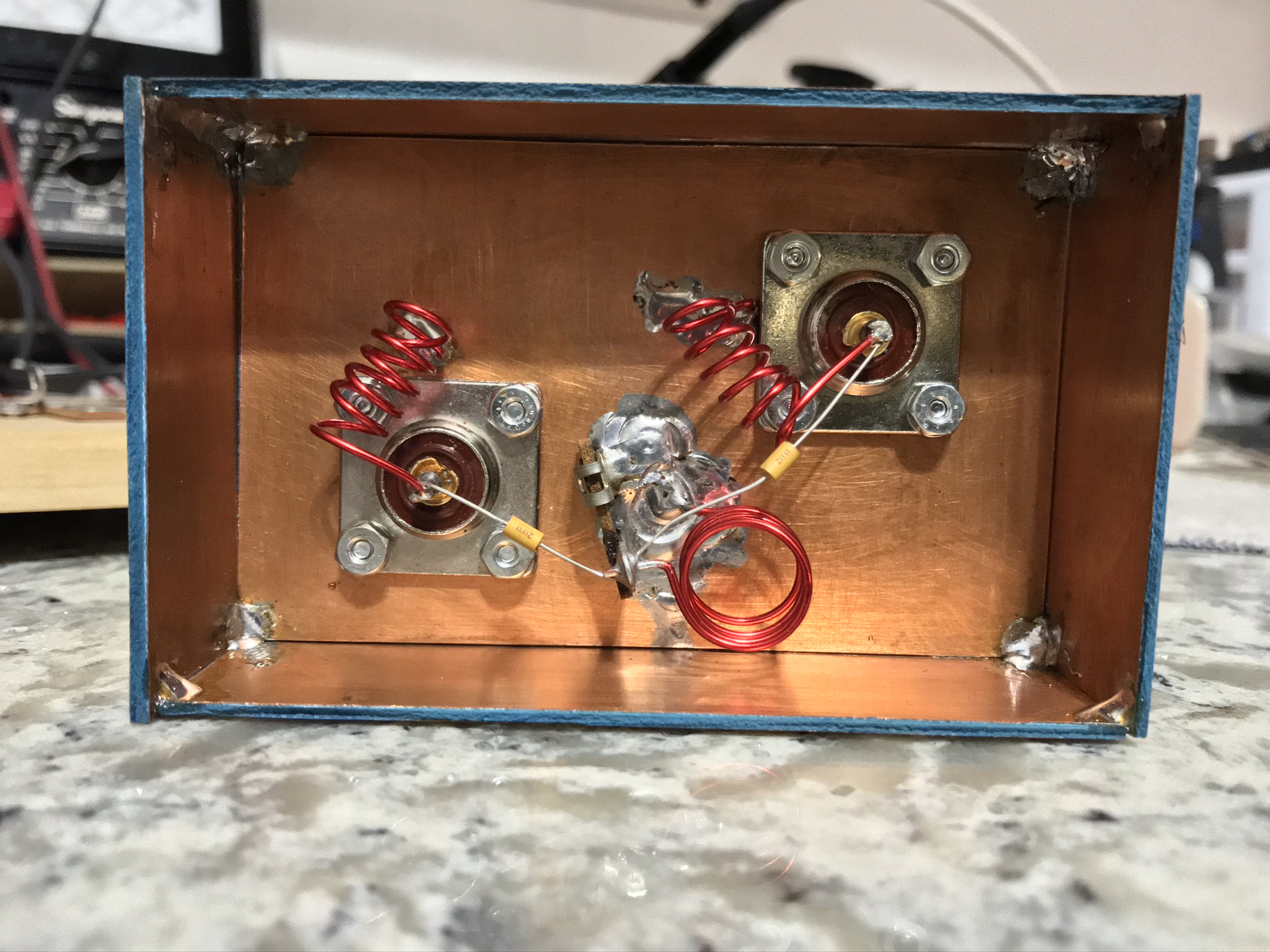
A planned trip into an area with a closer spacing between urban and rural areas a couple of years ago made leaving both antennas mounted more convenient. I was not particularly concerned about the VHF-UHF signals damaging the HF front end because of the IC-7000 antenna matcher, but there was no similar protection for the UHF-VHF receiver. To address this, I designed and built a high pass filter into a small enclosure that I built from double sided PC board material.

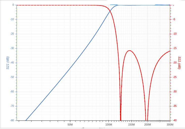
I used one of the calculators I found on the RF Tools website to come up with appropriate values. I chose a fifth-order Chebychev design, with a 120 mHz nominal cutoff frequency and 0.1 dB passband ripple.
Schematic
Figure 14 – Hi Pass Filter Schematic
Plots
Figure 15 – Hi Pass Filter Response

The response plots looked good, so I used another online calculator to determine the coil design. I selected 18 ga. wire for the coils to make them rigid enough to tolerate road vibration.
Inductance Turns Dia. Length
56 nH 4.0 0.25 in. 0.35 in
33 nH 3.0 0.25 in. 0.3 in
The completed filter is shown in Figure 16. The filter could have been built more compactly, as long as you maintain reasonable spacing between the coils and keep all of them mutually perpendicular. This orientation minimizes coupling between the inductors. I left the bottom cover off to enable access for adjustment should that prove to be necessary.
If you have access to a VNA, you may want to verify the response of the filter. I ran the filter for several years without checking, but a recent purchase added to my test bench enabled checking. I was very pleased with how closely the filter matched despite no tuning!

Hi Pass Filter
Figure 16 – Hi Pass Filter

TOP

Parts list

Antenna mount

Electrical

Remote head mount

Figure list

  1. Antenna mount front view
  2. Antenna mount top view
  3. Installed antenna mount
  4. Upper grounding lug
  5. Coax cable feed-through
  6. Coax cable routing
  7. Coax cable routed through cable guide
  8. AT7000 installation
  9. Control head fixture
  10. Control head fixture details
  11. Control head installation
  12. Transceiver installation
  13. Completed antenna installation
  14. Hi Pass Filter Schematic
  15. Hi Pass Filter Response
  16. Hi Passs Filter
TOP